Get Acquainted with the Network Map
The ARM's Network Map page provides an uncluttered, operator-friendly summary of the entire IP telephony network. By default, the page displays all VoIP entities managed in the telephony network. In the page, you can view node information and perform network map actions. The page shows the four main network entities that comprise the network topology (see here for an explanation of each):
| ■ | Node |
| ■ | VoIP Peer |
| ■ | Peer Connection |
| ■ | Connection |
| ➢ | To open the Network Map page: |
| 1. | In the Dashboard, click Discover more, or navigate to Network > Map; by default, the Network Map page displays all VoIP entities managed in the network. |
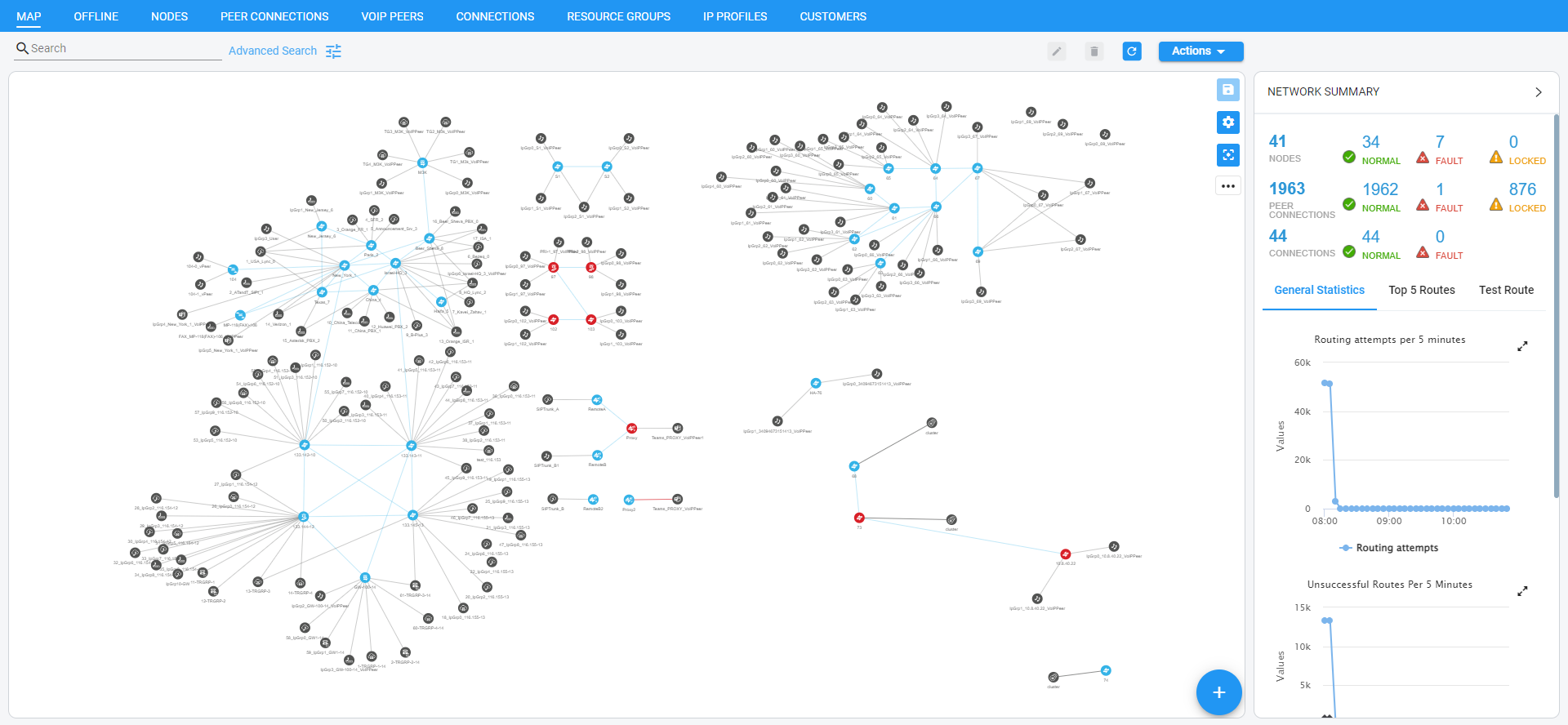
| 2. | Use the following legend as a reference to the preceding figure. |
Network Map page
|
GUI Area |
Description |
|||||||||||||||||||||||||||||||||
|---|---|---|---|---|---|---|---|---|---|---|---|---|---|---|---|---|---|---|---|---|---|---|---|---|---|---|---|---|---|---|---|---|---|---|
|
|
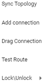
Click to select an action:
|
|||||||||||||||||||||||||||||||||
|
|
Click to select a Layer by which to filter the Network Map page:
|
|||||||||||||||||||||||||||||||||
|
Toolbar |
Toolbar icons let you navigate to the following ARM pages: |
|||||||||||||||||||||||||||||||||
|
|
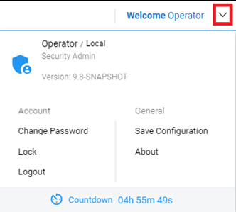
Located in the uppermost right corner of the page on the toolbar.
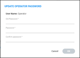
The ‘Update Operator Password’ screen then opens:
|
|||||||||||||||||||||||||||||||||
|
|
Saves entities' positions in the Network Map after they're moved. |
|||||||||||||||||||||||||||||||||
|
|
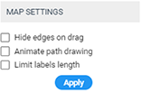
Map settings (opens the Map Settings pop-up menu):
|
|||||||||||||||||||||||||||||||||
|
|
Center map; centers the Network Map in the middle of the page. |
|||||||||||||||||||||||||||||||||
|
|
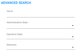
Enables you to locate specific information in the Network Map page, Routing page, Users page, Alarms page and Settings pages.
|
|||||||||||||||||||||||||||||||||
|
Main Screen |
The Network page displays a Map view of network entities. |
|||||||||||||||||||||||||||||||||
|
Summary Panes |
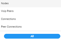
The Network Map page displays these summary panes:
|


| 3. | Use the following table as reference to each of the network entities that comprise the network topology. |
Network Entities
|
Icon |
Explanation |
||
|---|---|---|---|
|
Node |
|
Indicates an AudioCodes SBC communicating with the ARM. It's part of the ARM network topology. Blue = operative state available/logging in Red = operative state unavailable/unrouteable Orange = operative state logged out Strikethrough = locked No strikethrough = unlocked |
|
|
|
Indicates an AudioCodes gateway communicating with the ARM. It's part of the ARM network topology. Blue = operative state available Red = operative state unavailable INVALID CONFIGURATION Orange = operative state logged out Strikethrough = locked No strikethrough = unlocked |
||
|
|
Indicates a hybrid AudioCodes device (AudioCodes' Gateway and SBC in one). Blue = operative state available Red = operative state unavailable INVALID CONFIGURATION Orange = operative state logged out Strikethrough = locked No strikethrough = unlocked |
||
|
|
Indicates a third-party, non-AudioCodes device (such as Teams) communicating with the ARM. It's part of the ARM network topology. |
||
|
VoIP Peer
|
Indicates a non-AudioCodes device or entity that is also part of the ARM network topology: Teams, PBXs, SIP trunks, other vendors' SBCs / gateways. These devices participate in processing ARM network calls and are connected to Nodes by 'Peer Connections'. The ARM operator can configure one of six VoIP Peer types. |
||
|
|
Teams |
||
|
|
SIP trunk |
||
|
|
PSTN |
||
|
|
IP phones |
||
|
|
IP PBX |
||
|
|
Legacy PBX |
||
|
Connection |
|
Indicated by a blue line (available) or a red line (unavailable). Joins two Nodes. Calls can be routed between two Nodes only if there is a Connection between them. Defined by adding an IP Group (at Node level). From AudioCodes' gateway/SBC perspective, a ‘Connection’ is an 'IP Group'. Connections between Nodes are added by the ARM operator. |
|
|
Peer Connection |
|
Indicated by a black line between a Node and a VoIP Peer. Represents a group of routing destinations/sources (connections to a VoIP Peer), ‘last mile’ connectivity. From AudioCodes' gateway/SBC perspective, a Peer Connection is a ‘PSTN Trunk Group’ or ‘IP Group’. Red line = administrative state is unlocked / operative state is unavailable (no connection between the AudioCodes device and the remote device) / predeleted (IP Group was deleted from the device) Black line through a red sphere = unavailable and locked Black line through a black sphere = available but locked Operators can lock / unlock a Peer Connection as well as select a directional based lock / unlock which allows for example stopping only traffic towards a specific VoIP Peer (for example, a specific IVR) while calls coming from this VoIP Peer will still be routed to their destination. The feature can be used to perform a graceful stoppage of traffic for maintenance reasons (for example). The feature is essential for IVR VoIP Peers when there are always calls in a queue that are not yet connected to an agent. From the IVR’s perspective, the connection to the agent is outbound calls; without the uni-directional lock feature, calls fail. The Map page and Peer Connections page indicate a Peer Connection's directional lock. |
|